Hacking a Loewe TV Remote Control
Getting to know the MC9S08RD32 microcontroller
I found two Loewe TV remote controls at the local thrift shop. They felt hefty and oozed the quality you expect from Loewe. At 50 cents each I decided to take them home. You never know how they can be useful in a future project.
While cleaning them I noticed something surprising. They contained a brand-name flash programmable microcontroller. Albeit an old and a bit obscure one, but hey it put the remote control in its own project.
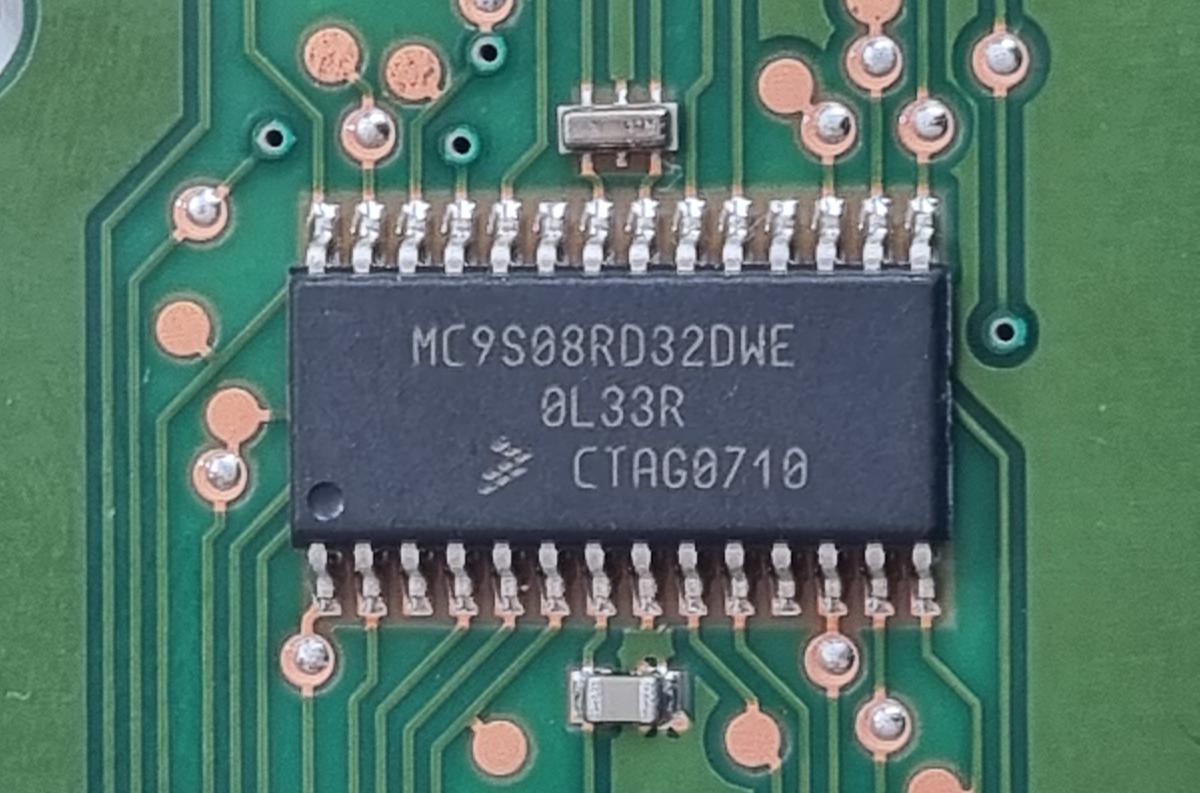
The microcontroller
The microcontroller is a Motorola/Freescale MC9S08RD32DWE with 32K flash and 2k of RAM. More advanced members of the family provide more flash, an analog comparator and/or SPI.
| Device | FLASH | RAM | Analog Comparator | Serial | SPI |
|---|---|---|---|---|---|
| 9S08RG32/60 | 32K/60K | 2K/2K | Yes | Yes | Yes |
| 9S08RE8/16/32/60 | 8/16K/32K/60K | 1K/1K/2K/2K | Yes | Yes | No |
| 9S08RD8/16/32/60 | 8/16K/32K/60K | 1K/1K/2K/2K | No | Yes | No |
These device provide a CMT (Carrier Modulator Timer) module that is specifically targeted at remote control applications. It allows the generation of infrared waveforms with minimal software overhead. Nice!
The CPU inside the device is HCS08.
Trying to determine usage of each pin
The pins driving the indicator leds and the infrared led can easily be found by tracing the pcb. The indicator leds are all connected to port B, the infrared led is connected to the IPO pen (no surprise here as IPO is the output of the Carrier Modulator Timer).
The usage of the other pins is not clear from the PCB without removing the keys on the other which seem to be glued to the PCB. I expect them to implement some kind of scanning matrix. Measuring the voltage and impedance to the rails provided a bit more information.
Measuring voltage and impedance to GND and Vdd during idle (sleep) state
| Known purpose | Pin number | Name | Voltage | Impedance to GND | Impedance to Vdd | Conclusion |
|---|---|---|---|---|---|---|
| 1 | A5 | 3 V | 16 MΩ | 25 kΩ | input (pull-up) | |
| 2 | A6 | 3 V | 16 MΩ | 25 kΩ | input (pull-up) | |
| 3 | A7 | 3 V | 16 MΩ | 25 kΩ | input (pull-up) | |
| LED-TV | 4 | B0 | 3 V | 16 MΩ | 40 Ω | drive(1) when off |
| LED-REC | 5 | B1 | 3 V | 16 MΩ | 40 Ω | drive(1) when off |
| LED-DVD | 6 | B2 | 3 V | 16 MΩ | 40 Ω | drive(1) when off |
| 7 | VDD | 3 V | ||||
| 8 | GND | 0 V | ||||
| LED-IR | 9 | IRO | 0 V | 20 Ω | 16 MΩ | drive(0) when off |
| LED-RADIO | 10 | B7 | 3 V | 16 MΩ | 40 Ω | drive(1) when off |
| 11 | C0 | 0 V | 40 Ω | 16 MΩ | drive(0) | |
| 12 | C1 | 0 V | 40 Ω | 16 MΩ | drive(0) | |
| 13 | C2 | 0 V | 40 Ω | 16 MΩ | drive(0) | |
| 14 | C3 | 0 V | 40 Ω | 16 MΩ | drive(0) | |
| 15 | C4 | 0 V | 40 Ω | 16 MΩ | drive(0) | |
| 16 | C5 | 0 V | 40 Ω | 16 MΩ | drive(0) | |
| 17 | C6 | 0 V | 40 Ω | 16 MΩ | drive(0) | |
| 18 | C7 | 0 V | 40 Ω | 16 MΩ | drive(0) | |
| 19 | BKGD | 3 V | ||||
| 20 | RESET | 3 V | ||||
| 21 | XTAL | - | ||||
| 22 | EXTAL | - | ||||
| 23 | D6 | 0 V | 40 Ω | 16 MΩ | drive(0) | |
| 24 | A0 | 2.25 V | 16 MΩ | 38 MΩ | input | |
| 25 | A1 | 3 V | 16 MΩ | 25 kΩ | input (pull-up) | |
| 26 | A2 | 3 V | 16 MΩ | 25 kΩ | input (pull-up) | |
| 27 | A3 | 3 V | 16 MΩ | 25 kΩ | input (pull-up) | |
| 28 | A4 | 3 V | 16 MΩ | 25 kΩ | input (pull-up) |
Port A (A1 - A7) seems to be used as inputs with a pull-up to Vdd. Port C (C0 - C7) are outputs, all at 0V during idle. Using port A as the input side of the matrix is to be expected, because this port has an alternative function called keyboard interupt (KBI1). KBI1 can issue an interrupt on the transition from high to low on any of the pins, or what I think happens here is to wake the processor from one of the low power sleep modes.
Pin A0 is probably not used here as it is different than the other pins on port A. A0 can only be used as input, does not have a clamp diode to VDD and should therefore not be driven above VDD. Also, A0 does not pullup to VDD when internal pullup is enabled in the corresponding register.
During idle, with all pins on port C low, pressing any key on the remote will bring one of the inputs on port A low and wake the processor. After waking up, the processor will probably put port C to all ones expect for one bit. By cycling this single low bit from position 0 to 7 and monitoring port A, it can dermine which key was pressed and send the corresponding IR code.
Can we (re-)program it?
Now we understand how it probably works, it is important to find out if we can alter it to create the ultimate personalized remote control. We obviously need a programmer.
Programming these old Freescale devices can be done with expensive tools from NXP and some niche companies or much cheaper using hard and software from the (open source) USBDM project.
I searched Aliexpress for USBDM devices and found them relatively expensive and it was pretty unclear which versions of USBDM hardware they would ship. I saw a lot of different pcbs and the only one I could correlate to info from the USBDM project page apperently had some issues.
The datasheet revealed that the debugging interface of this and other HCS08-based chips is relatively simple. Also there is a clear procedure to probe the interface to determine the timing of the interface. By pulling the BDM pin low for a relatively long time, the chip will respond with a precisely timed pulse. You can measure that pulse to determine the speed of the interface.
This sync pulse measurement appealed to me as a nice starting point. I decided to give it a try and set something up with a STM32 black pill board and to call the device miniBDM. BDM refers in the world of Freescale to the Background Debug Mode for debugging and programming devices such as the HCS08 (see AN3335). My approach here with the miniBDM is similar to the bus-pirate: a serial device with a menu that you can use to play around with the target and a command mode that can be controlled by software.
The debugging interface of these chips is basically a single wire: the BKGD pin. It has a pull-up resistor to default it to logic 1 when it is not driven low by either host or target. To solve the issue that the level returns relatively slowly to 1 by the pull-up resistor, both host and target will drive the pin to logic 1 for a very short period after a logic 0 signal to ensure sharp pulses. This mechanism works very well as can be seen in the scope picture below.
The SYNC request is started by the host through driving the BKGD pin low for a relatively long time (longer than would ever occur during normal BDC communications). The target, upon detecting the SYNC request:
- Waits for BKGD to return to a logic high
- Delays 16 BDC clock cycles
- Drives BKGD low for 128 BDC clock cycles
- Removes all drive to the BKGD pin so it reverts logic high
The scope shows the sync pulse on the BKGD pin:

Success! On the scope we see that the high pulse of 16 cycles takes 2 µs, the low pulse of 128 cycles takes 16 µs. Both lead to a cycle length of 125 ns, which means the BDM clock is running at 8 MHz. Defenitely a realistic value.
        Welcome to miniBDM: stm32-based HCS08 BDM dongle
(c) 2023 - Martin van der Werff - (github at newinnovations.nl)

You pressed P: sync pulse measurement
DONE. high = 60 ticks, low = 510 ticks
      value for use with USBDM = 956
The miniBDM performs its measurements using a timer running at 32 MHz. So 510 ticks means 510 / 32 * 10^6 = 15.94 µs.
More on the miniBDM and how it turned into a full programmer for this chip: see here (TBD).
Testing the programmer: animating the leds

Sending IR
A lot can and has to be said about how to send IR signals. Luckily Freescale has already done that for us in AN3053: Infrared Remote Control Techniques on MC9S08RC/RD/RE/RG Family. And the corresponding example code is still available from NXP. The code can almost be used right out of the box and provides routines for Philips RC5, Sony SIRC and NEC protocols. Only Philips RC6 is missing.
Determining the keyboard matrix
The following code was used to determine the keyboard matrix. Upon detecting a keypress it will send out the scan mask and input using the infrared transmitter.
for (;;) {
    for (mask = 0x01; mask; mask <<= 1) {
        PTCD = ~mask;
        matrix_in = ~PTAD;
        PTCD = 0xff; // don't rely on the pull-ups to restore port A pins to 1 (see notes)
        if (matrix_in) {
            PDP_protocol(mask, matrix_in); // send IR using NEC protocol
            Cpu_Delay100US(5000); // 0.5 sec
        }
    }
}
Notes
- The remote control uses pin A0 in the matrix. I did not expect that! The microcontroller does not support a pull-up for A0 and none is provided on the board. This pin is floating in the breeze and can easily pick-up stray charges and provide false inputs. On several occasions it kept returning low values after a key was released and I had to switch the power off to the remote.
- That is why I updated the code to output all ones on port C after polling port A to bring any scanned pin on port A back to logic 1. The was also required for the other pins on port A. The pull-ups return relatively slow to 1 and could cause false key press indications on the scan of the next column.
- Pin A7 is not used in the matrix and supports internal pull-up unlike A0. So why did they use pin A0 and not A7?
- Pin C7 is not used, so we can stop scanning after mask 0x40
After pressing all the keys and writing down the IR values, this is the keyboard matrix of the Loewe TV remote control.
| pin C0 | pin C1 | pin C2 | pin C3 | pin C4 | pin C5 | pin C6 | pin C7 | |
|---|---|---|---|---|---|---|---|---|
| pin A0 | 1 | 2 | 3 | tv | text | red | up | - |
| pin A1 | 4 | 5 | 6 | rec | menu | green | down | - |
| pin A2 | 7 | 8 | 9 | dvd | end | yellow | ok | - |
| pin A3 | mute | 0 | standby | radio | info | blue | left | - |
| pin A4 | timer | wide | speaker | rewind | play | forward | right | - |
| pin A5 | epg | assist | pip | record | pause | stop | - | - |
| pin A6 | volume up | volume down | program up | program down | - | - | - | - |
| pin A7 | - | - | - | - | - | - | - | - |
Power consumption during stop states
TBD
Other remotes with the MC9S08RD32
TBD
Final code
TBD